Emmequerung Tunnel
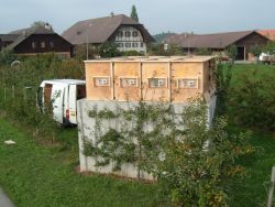
Emmequerung tunnel is in Switzerland, about 20 km north-east of Berne. It is approximately 1.6 km long and has two airshafts. The airflow measurements were made at the top of the south airshaft, which is approximately 542 m from the south portal. In addition, pressure measurements were made at a location about 462 m from the south portal (i.e. 80 m before the shaft).
The tunnel cross-section is uniform in the region under consideration. Its perimeter and cross sectional area are approximately 33.7 m and 75.9 m2 respectively. The wall surface is smooth concrete.
Schematic of tunnel
South shaft
The main part of the south airshaft is vertical and has an approximately square cross-section with sides of 3.51 m. Its structural portal is approximately 7.8 m above the tunnel centreline so the portal of the 1.25 m high box structure built by DTR was approximately 9 m above the tunnel centreline.
The centre-line of the shaft is to the east of the tunnel so airflows between the shaft and the tunnel have a strong lateral component. The geometrical arrangement at the base of the shaft is documented photographically in these web pages. It is depicted schematically in the following sketch.
Tunnel cross section at airshaft
DTR Measurement Enclosure
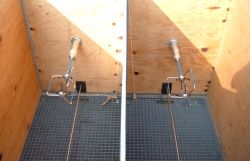
The top of the shaft is protected by security grilles mounted on steel I-beams. There are eight grilles in a 2 x 4 arrangement. The grilles - and, in particular, the I-beams - had a major influence on the chosen method of supporting the flow sensors. A set of 8 blade flow meters for measuring up-flows was attached to the undersides of the grilles. A second set for measuring down-flows was supported above the grille, vertically above the first set. Provision was made for one ultrasonic anemometer above each grille (although only six were available for use in any one run).
All sensors above the grilles were mounted on outer and inner walls of a 1.25 m high plywood box structure. The outer walls were aligned to create a simple extension of the concrete shaft walls. The inner walls, mounted vertically above the centre lines of the I-beams, were provided partly for structural simplicity and partly to simplify the interpretation of the individual flow measurements. In the particular case of purely vertical upflow, the inner walls will have had negligible influence on the flow.
|
|