Ultrasonic Anemometer Data - Northbound
This page contains data measured using ultrasonic anemometers during the following Northbound train runs:
| Train Run Number | Speed (km/h) | Data File |
|---|---|---|
| 35337 | 177.5 | 35337-s04.dat |
| 35339 | 198.5 | 35339-s06.dat |
| 35343 | 204.0 | 35343-s08.dat |
| 35353 | 196.0 | 35353-s13.dat |
| 35361 | 198.5 | 35361-s15.dat |
| 35365 | 147.5 | 35365-s17.dat 35365-s18.dat (Data continues into second file) |
The data files can be viewed in a text editor and can be downloaded from http://www.thermotun.com/airshaft/ultrasonic/ultrasonic-northbound-dat.zip
Example Graphs
The following example graphs have been produced from data file 35337-s04.dat
| The measurement enclosure on top of the airshaft was divided into 8 compartments (see photographs of the airshaft). The layout of the graphs represents the distribution of 6 ultrasonic anemometers in the airshaft as viewed from above. Each ultrasonic sensor measured flow data in 3 directions. Each direction is shown in a different set of graphs below. The speed of sound was estimated by the ultrasonic sensors and is included in a further set of graphs. |
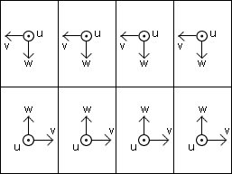 Diagram of airshaft from above showing orientation of ultrasonic sensors. |
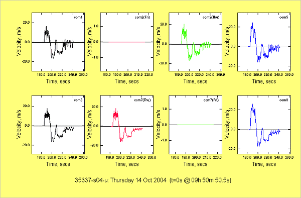
u direction: vertical airflow component (+ve = up the shaft)
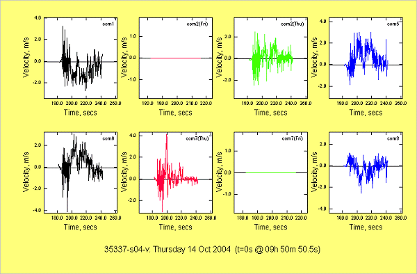
v direction: lateral airflow component (+ve = right to left in the top boxes, left to tight in the bottom boxes)
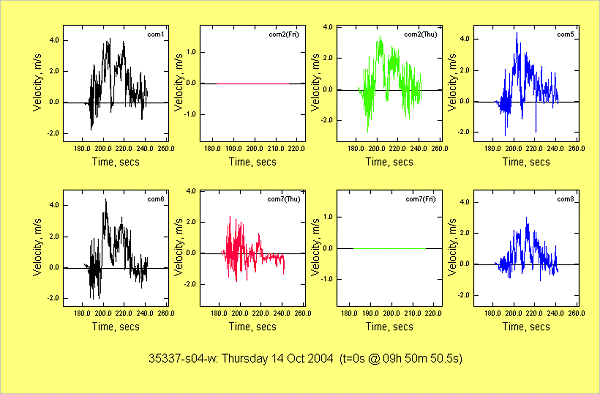
w direction: longitudinal airflow component (+ve = inwards from shaft wall)
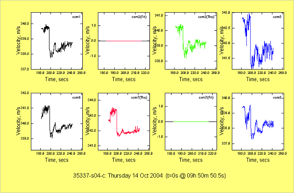
c: speed of sound (approx)
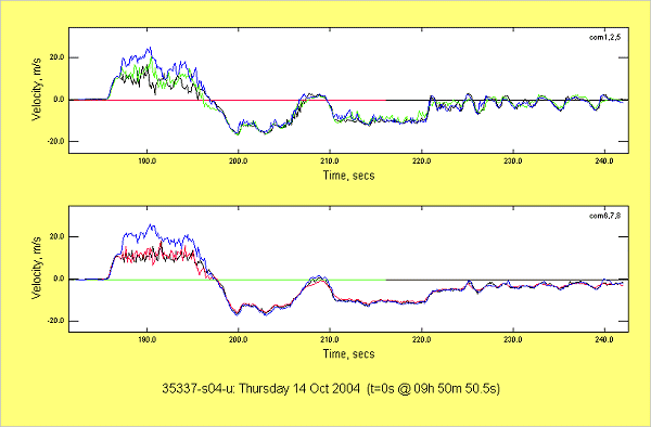
u direction: Comparison between two sets of three ultrasonic sensors.